Give each component a specific job
| Candidate | Published role or fact | Do not assume |
|---|---|---|
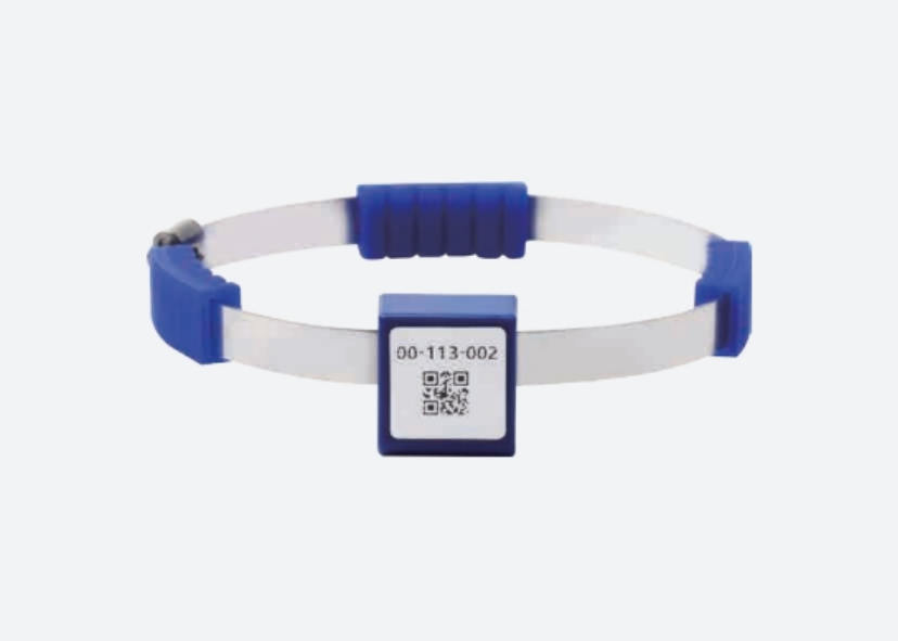
| W-S01 | CT-powered wireless temperature sensor; listed load current > 3 A | Readings remain available below the required power condition |
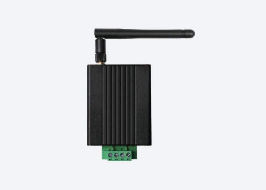
| W-D21 | Receiver; 12 points, RS485 Modbus-RTU | Every sensor revision or a default host register map is supported |
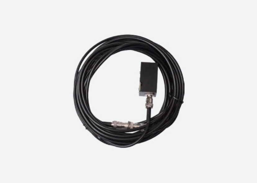
| W-S03 | Fibre-optic temperature-sensing option | It is an interchangeable CT-powered wireless sensor |
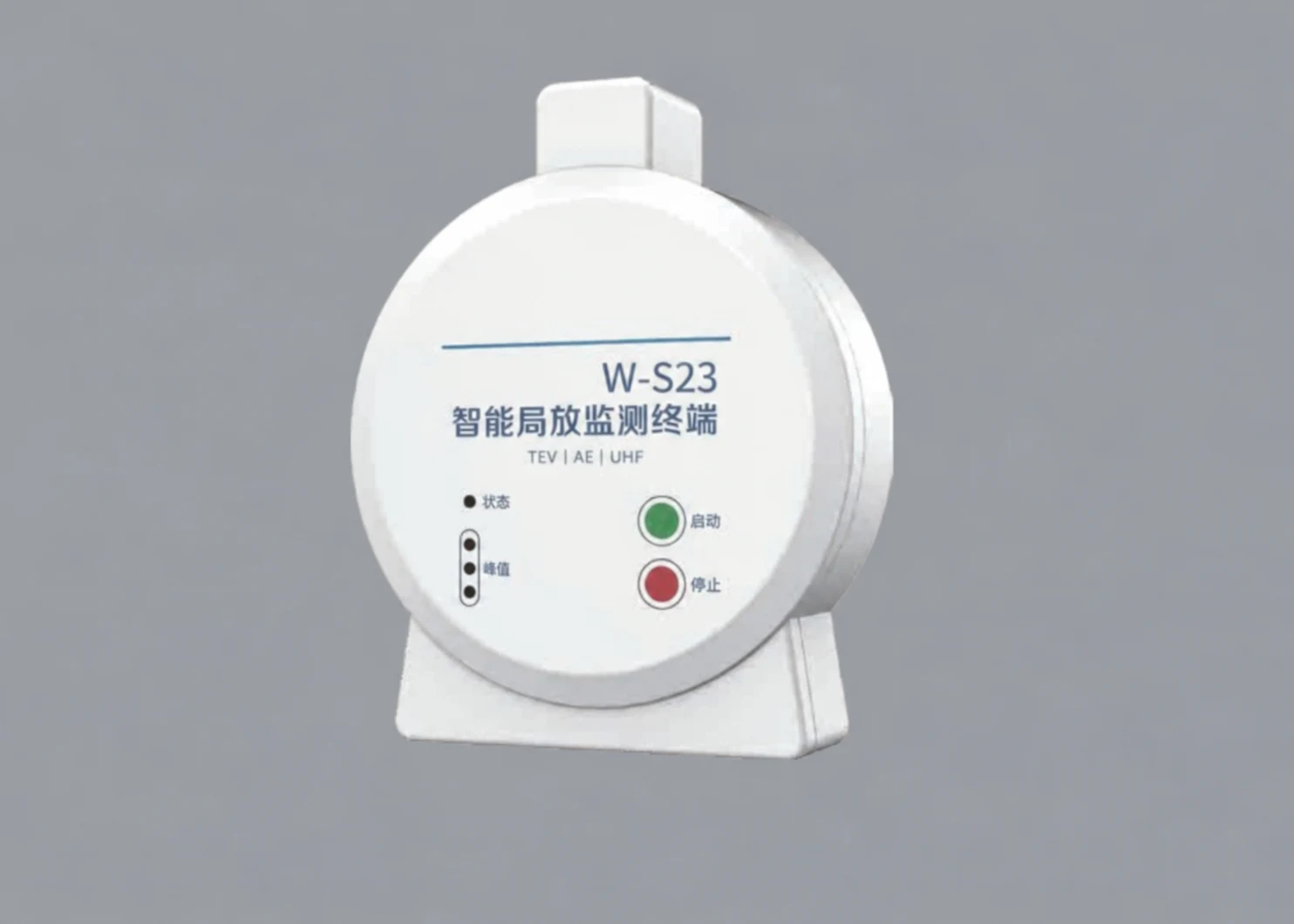
| W-S23 | Partial-discharge monitoring option | It is a drop-in temperature sensor or a complete safety system |
Confirm the intended sensor/receiver revisions and configuration with the model-specific documents. The table separates tasks; it does not certify a combined kit.
Resolve power and radio availability separately
Record normal and minimum current at each proposed CT-powered measuring point, including the operating states when data is needed. The minimum-current worksheet makes those states explicit without inventing startup or dropout behaviour.
For the installed arrangement, record cabinet boundaries, partitions, receiver position and relevant operating states. Use the cabinet test matrix to separate open-space figures from observations in a defined layout. No radio range is promised for a site from this page.
Prepare the receiver-to-host handoff
The public Modbus serial guide and application specification explain general interfaces and protocol behaviour. They do not define a proprietary receiver map.
Request the exact register/serial information, scaling and available status fields. Agree who maps sensor identity to the physical measuring point, who treats old/unavailable data and who defines alarm logic. A displayed temperature alone does not establish a complete protection or diagnostic function.
Information to bring into the project discussion
- Equipment type, proposed measuring points and data-availability requirement.
- Current conditions and permitted mounting/installation window.
- Cabinet layout, receiver location and relevant obstructions.
- Existing host, communications and available revision information.
- Destination market, sample quantity and the decision the evaluation must support.
Electrical installation, isolation and clearances remain with the qualified parties responsible for the equipment. The first discussion should turn missing inputs into named tasks and identify a reviewable sample scope—not promise installation or system acceptance before the configuration is defined.
Sources & review scope
The component facts are manufacturer-stated product summaries. The table identifies review candidates and questions, not an approved bill of materials, a site installation procedure or a protection-system claim.