Hong Kong contact. Mainland China manufacturing.
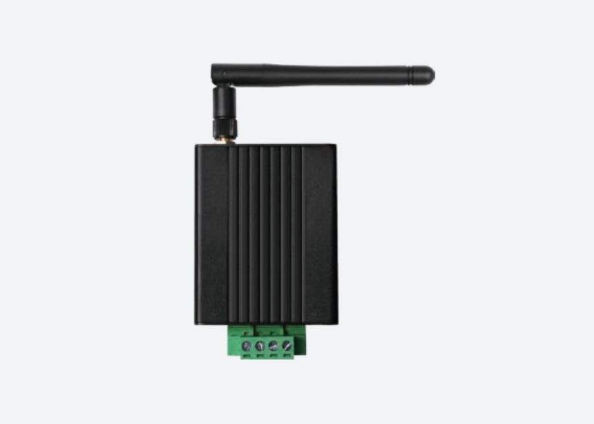
W-D21 Wireless Temperature Receiver (RS485 Modbus) — product imageEnlarge image
W-D21 Wireless Temperature Receiver (RS485 Modbus) — product image, enlarged
Reference image. Appearance and markings are confirmed for the selected model.
Sensing & Positioning

W-D21 Wireless Temperature Receiver (RS485 Modbus)

Model: W-D21

A 12-point wireless temperature receiver with a 5–28 V DC supply and RS485 Modbus-RTU output, for cabinet-monitoring integration.

Power supply
5–28 V DC
Communication interface
RS485 (Modbus-RTU)
Wireless sensors supported
12 points
Wireless range
≤ 60 m

Sample availability, pricing and shipping are confirmed for your configuration. Specifications are manufacturer-stated.

Specifications

W-D21 Wireless Temperature Receiver (RS485 Modbus) specifications
ParameterStated value
Model W-D21
Power supply 5–28 V DC
Communication interface RS485 (Modbus-RTU)
Wireless sensors supported 12 points
Wireless range ≤ 60 m
Dimensions 55 × 30 × 69 mm (excluding antenna)
Operating environment −20 to +65 °C, ≤ 97% RH, altitude ≤ 4000 m
Typical locations HV/LV switchgear, transformers, cables
Compatible sensors Compatible wireless temperature sensors in the same series

Values are taken from manufacturer documentation and apply to the listed configuration. Confirm the current model-specific document, conditions and revision before procurement.

Integration notes

Measurement, installation and host interfaces

Confirm the measuring point, power supply, installation constraints and data path. Sensor, probe, receiver and host-system requirements vary by model; review the product-specific notes below before choosing the evaluation configuration.

Application notes & selection checklist

A receiver between the sensors and the host

W-D21 collects up to 12 wireless temperature points and exposes data over RS485 Modbus-RTU. Define the measuring-point list and host-system requirements together. The published point count and wireless-range figure are separate constraints; neither proves reception through the proposed cabinet arrangement.

Confirm the sensor and register configuration

Request the supported sensor revisions, point-addressing method, register information and data-update behaviour for the receiver firmware. Sensors listed in the same series are candidates for review, not a reason to assume every combination is already configured or validated.

The 5–28 V DC supply window and dimensions excluding the antenna should also be reviewed against the intended enclosure. Include the antenna envelope and the listed operating environment when discussing placement.

Check the complete data path

For the sample, identify each sensor point and verify how the host receives and labels its readings. Record unavailable or delayed data as well as temperature values. Agree on alarm ownership and the host’s treatment of missing measurements. If more than 12 points are required, review a separately specified receiver rather than applying another model’s capacity to W-D21.
Samples & customization

Share the interfaces, mechanical envelope and changes you need. We coordinate the review of feasibility, sample configuration, minimum quantities, tooling and commercial terms. Agree on the test scope and responsibilities before evaluation.

How we approach validation

Documentation

Model-specific datasheet

Request the current datasheet, interface information and revision for your project.

Request the datasheet

Applications to review

These paths help frame a review. A listed component is not a pre-validated system configuration.