Hong Kong contact. Mainland China manufacturing.
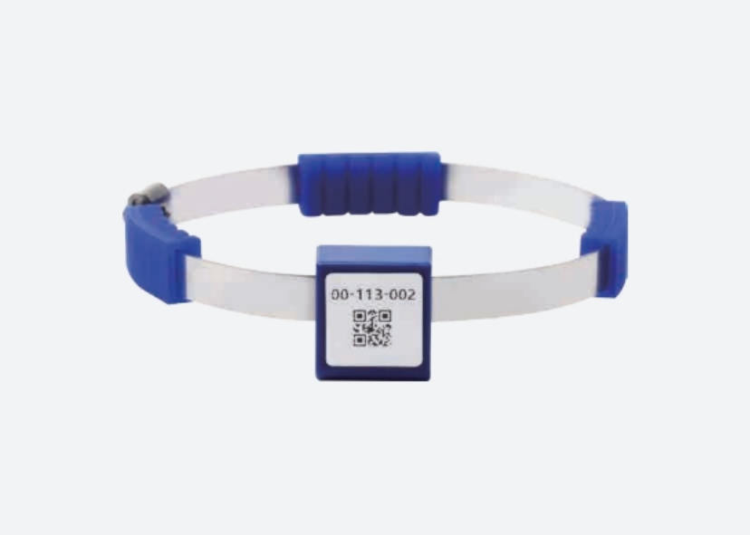
W-S01 CT-Powered Wireless Temperature Sensor — product imageEnlarge image
W-S01 CT-Powered Wireless Temperature Sensor — product image, enlarged
Reference image. Appearance and markings are confirmed for the selected model.
Sensing & Positioning

W-S01 CT-Powered Wireless Temperature Sensor

Model: W-S01 (W-S01F outdoor waterproof version)

A CT-induction wireless temperature sensor for switchgear joints and busbars, with a listed load-current condition above 3 A and a 433 MHz radio link.

Power supply
CT induction, load current > 3 A
Measurement range
−40 to 200 °C
Measurement error
±1 °C
Radio frequency
433 MHz

Sample availability, pricing and shipping are confirmed for your configuration. Specifications are manufacturer-stated.

Specifications

W-S01 CT-Powered Wireless Temperature Sensor specifications
ParameterStated value
Model W-S01 (W-S01F outdoor waterproof version)
Power supply CT induction, load current > 3 A
Measurement range −40 to 200 °C
Measurement error ±1 °C
Radio frequency 433 MHz
Communication distance ≤ 180 m open space; 60 m inside a cabinet
Dimensions 24.5 × 26.3 × 13.6 mm
Installation Strap mounting
Housing Flame-retardant material, V-0 (W-S01F: IP68)

Values are taken from manufacturer documentation and apply to the listed configuration. Confirm the current model-specific document, conditions and revision before procurement.

Integration notes

Measurement, installation and host interfaces

Confirm the measuring point, power supply, installation constraints and data path. Sensor, probe, receiver and host-system requirements vary by model; review the product-specific notes below before choosing the evaluation configuration.

Application notes & selection checklist

Minimum current is part of sensor selection

W-S01 draws operating power through CT induction. The listed load-current condition is greater than 3 A at the measuring point. Confirm the lowest current where a reading is required, including idle or intermittent operation; the nominal rating of the cabinet does not answer that question.

The documentation lists strap mounting on busbars, cable joints and switchgear contacts. Review the actual measuring point and installation constraints with the parties responsible for the equipment before planning a sample installation.

Identify the receiver and exact sensor version

A receiver such as W-D21 is a review candidate, subject to the supported sensor and firmware configuration. The open-space and in-cabinet communication figures have different conditions and should not be treated as one deployment guarantee.

W-S01F is the separately identified outdoor waterproof version. Its listed IP68 statement must not be applied to an unspecified W-S01 configuration.

Observe power-up and data availability

Agree on the reference measurement and the operating states to observe. Record minimum current, receiver location, reception and any gaps during low-current or recovery conditions. Treat temperature reporting and the host’s alarm or protection decisions as separate responsibilities.
Samples & customization

Share the interfaces, mechanical envelope and changes you need. We coordinate the review of feasibility, sample configuration, minimum quantities, tooling and commercial terms. Agree on the test scope and responsibilities before evaluation.

How we approach validation

Documentation

Model-specific datasheet

Request the current datasheet, interface information and revision for your project.

Request the datasheet

Applications to review

These paths help frame a review. A listed component is not a pre-validated system configuration.