Hong Kong contact. Mainland China manufacturing.
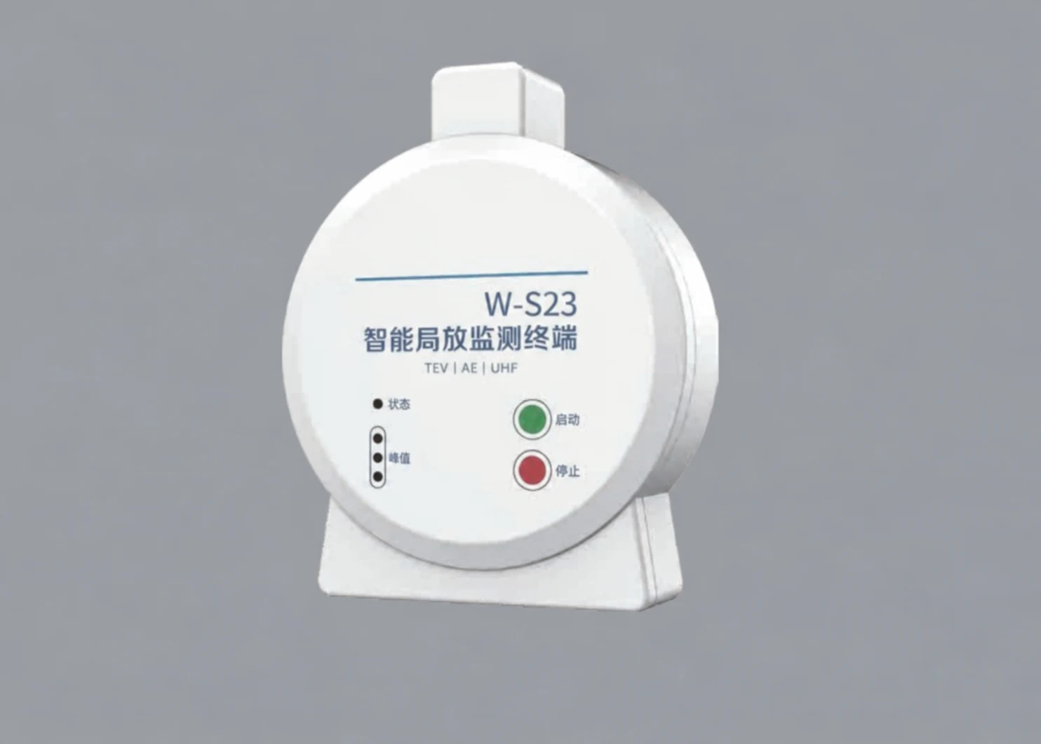
W-S23 TEV, Ultrasonic & UHF Partial Discharge Sensor — product imageEnlarge image
W-S23 TEV, Ultrasonic & UHF Partial Discharge Sensor — product image, enlarged
Reference image. Appearance and markings are confirmed for the selected model.
Sensing & Positioning

W-S23 TEV, Ultrasonic & UHF Partial Discharge Sensor

Model: W-S23

A partial-discharge monitoring sensor combining TEV, ultrasonic and UHF detection channels, for switchgear and equipment-condition evaluation.

Power supply
16–24 V DC, ripple ≤ 1%
Linearity error
≤ ±20%
Ultrasonic: centre frequency
40 ± 1 kHz
Ultrasonic: range / detection band
0–60 dBmV / 20–60 kHz

Sample availability, pricing and shipping are confirmed for your configuration. Specifications are manufacturer-stated.

Specifications

W-S23 TEV, Ultrasonic & UHF Partial Discharge Sensor specifications
ParameterStated value
Model W-S23
Power supply 16–24 V DC, ripple ≤ 1%
Linearity error ≤ ±20%
Ultrasonic: centre frequency 40 ± 1 kHz
Ultrasonic: range / detection band 0–60 dBmV / 20–60 kHz
TEV: detection band / range 3–100 MHz / 0–60 dBmV
TEV: pulse count error ≤ ±10%
UHF: detection band 500–1500 MHz
UHF: measurement level / accuracy −75 dBm / ±2 dBm
Compatible temperature sensors W-S15, W-S01, W-S02, W-S05

Values are taken from manufacturer documentation and apply to the listed configuration. Confirm the current model-specific document, conditions and revision before procurement.

Integration notes

Application conditions and evaluation scope

Confirm the required measurement function, installation environment, power and host interfaces. Related products are review candidates; the final system configuration and acceptance criteria need a project-specific assessment.

Application notes & selection checklist

Three detection channels, different quantities

W-S23 combines TEV, ultrasonic and UHF detection for equipment-condition monitoring. Each channel has its own listed band, range or measurement-level specification. Do not collapse these into one generic accuracy figure or treat a channel reading as a complete insulation diagnosis.

Define the monitoring and host requirements

The listed 16–24 V DC supply includes a ripple condition. Request the selected hardware’s data-interface and configuration documentation before planning the host connection; the presence of related temperature-sensor models in the catalogue does not define the complete data path.

The manufacturer positions the unit for high-voltage and ring-main switchgear and lists related temperature sensors. Their inclusion supports a configuration discussion, not a claim that the combined monitoring package has been validated for a particular cabinet.

Agree on interpretation before the sample

Identify the equipment, relevant detection channels, reference records and the people responsible for interpreting the results. Alarm thresholds and diagnostic conclusions need equipment-specific agreement. Any access to energised electrical equipment remains with the qualified parties responsible for the installation; this product overview is not an installation procedure or a protection-system approval.
Samples & customization

Share the interfaces, mechanical envelope and changes you need. We coordinate the review of feasibility, sample configuration, minimum quantities, tooling and commercial terms. Agree on the test scope and responsibilities before evaluation.

How we approach validation

Documentation

Model-specific datasheet

Request the current datasheet, interface information and revision for your project.

Request the datasheet

Applications to review

These paths help frame a review. A listed component is not a pre-validated system configuration.