Put energy and peak power in different columns
The following numbers are deliberately hypothetical. They show how to record a load, not what a customer device consumes.
| Illustrative state | Power | Time per day | Energy |
|---|---|---|---|
| Active | 8 W | 8 h | 64 Wh |
| Idle | 0.5 W | 16 h | 8 Wh |
| Total before any conversion losses | — | 24 h | 72 Wh/day |
Daily load energy = sum of each state's power × durationRecord startup and short peak demands separately: a daily energy total does not say whether an interface can supply a peak. Do not turn the 72 Wh example into a solar-module or battery-size recommendation without the remaining system inputs.
Choose the interface path the device actually uses
| Device arrangement | Starting comparison | Key unresolved input |
|---|---|---|
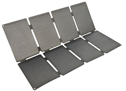
| Regulated portable input | 60 W folding charger | Accepted output profile, cable and behaviour when solar input changes |
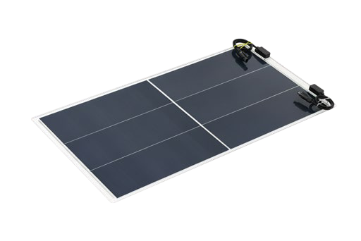
| Module plus separately selected controller | 100 W lightweight module | Complete controller/battery input windows and system design |
| Required operation through low/no solar | A defined storage and control architecture | Energy reserve, operating conditions and responsibility for sizing |
The folding charger lists a 20 W maximum USB-C PD output in its stated configuration. That is a port limit, not a guarantee of 20 W throughout the day. USB-IF’s Power Delivery description explains why the source, cable and receiving device must be considered together.
Complete the assumptions before estimating autonomy
State the operating location, exposure, orientation, shading and temperature conditions. Define when the device must keep operating without solar input and what it may do when energy is insufficient.
The PVGIS manual demonstrates that PV energy modelling requires site and system inputs. Its general modelling context does not validate a particular portable setup or remote device.
Make the sample answer a defined question
Keep the actual device mode, charging path, selected components and observation conditions with the results. A charging icon alone does not establish a daily energy balance. Identify whether the evaluation concerns a port, recovery after input interruption or another agreed behaviour.
Use solar wattage versus port output for the interface record and the OEM brief to separate known requirements from unresolved architecture. No complete autonomous power configuration is assumed by this shortlist.
Sources & review scope
The load calculation is a hypothetical planning example, not measured device consumption or a battery/array recommendation. Catalogue figures remain specific to their linked configurations.