Locate the conversion task in the architecture
| Project boundary | Published starting point | Decision still to close |
|---|---|---|
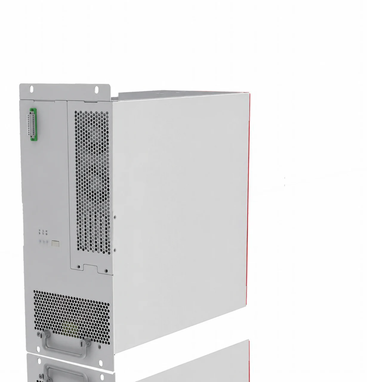
| Battery/DC side to AC system | PCS1-100K | Full battery range, AC conditions, control responsibilities and operating envelope |
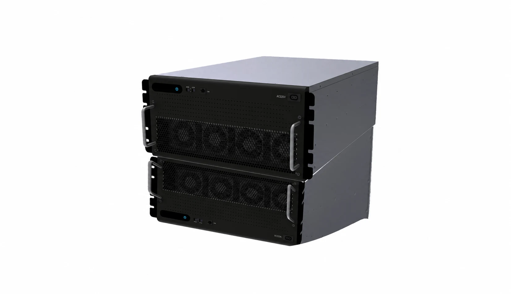
| DC voltage conversion | DC–DC converter family | Exact model, both interfaces, power-flow direction and selected control mode |
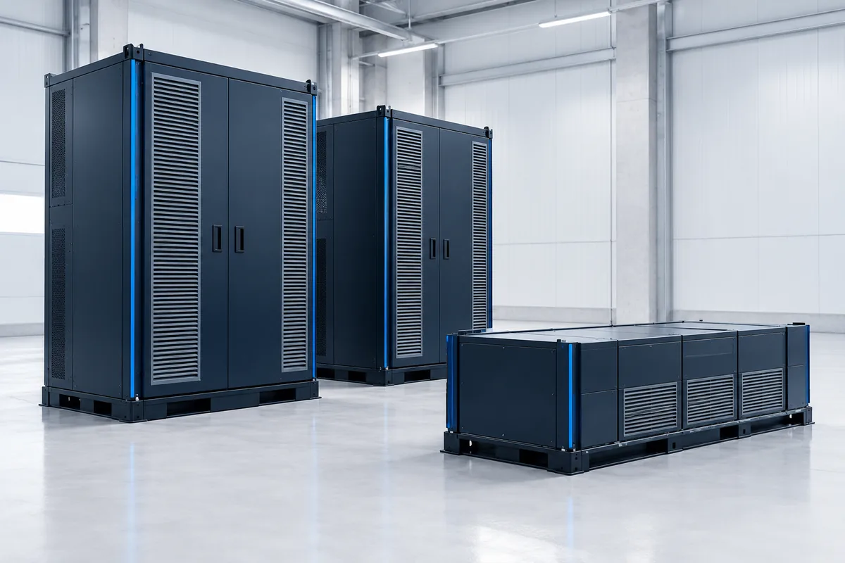
| Complete storage system | A project-specific architecture | Equipment, protection, enclosure, controls and responsible system engineer |
A product appearing in the second row does not establish that it is required by, or approved with, the PCS in the first row.
Do not silently resolve the kW/kVA distinction
The PCS entry lists 580–950 V DC, RS485 / CAN, IP20, and rated AC power of 100 kVA in its catalogue table. Its family title uses 100 kW. Ask for the active/reactive operating envelope instead of treating the units as identical.
The power-converter guide separates the units with a clearly illustrative calculation. It does not fill in an operating curve for this model.
The DC–DC family separately lists 300–850 V DC input, forced-air cooling and constant-voltage/current/power operating modes. Give the complete required input and output conditions rather than relying on nominal battery voltage or the model name alone.
Assign the interface and document questions
| Information | Who supplies the starting input? | What the review needs |
|---|---|---|
| Battery/DC operating limits | Customer/system engineer and battery documentation | Selected converter’s applicable limits |
| Control/BMS/supervisory interface | Owners of the connected equipment | Exact protocol/map and supported revisions |
| Enclosure and cooling | Installation/system designer | Model-specific mounting, airflow and environmental requirements |
| Destination-market scope | Project owner | The actual equipment/configuration and relevant acceptance evidence |
Modbus’s application specification illustrates the distinction between an application protocol and a physical interface. It does not supply a register map for either listed converter or establish that its RS485 interface uses that protocol.
Scope a component review before a system quotation
An initial outcome can be an agreed electrical window, a request for control documents or a defined sample configuration. Keep open responsibilities visible: who designs the system, who provides model-specific information and who accepts the final installation.
Bring the architecture, operating modes, market and project stage to the discussion. The page supports component sourcing and technical coordination; it does not represent a ready-approved commercial storage package.
Sources & review scope
The converter values come from the linked product entries. The boundary map is a review aid, not a wiring diagram, complete storage-system design or declaration of grid acceptance.